Dipl. Ing. A. Kutschelis & Sohn
Technische Lehrmittel Construktion
D- 59425 Unna
Germany
web: http://www.telc.de
mail: mail@telc.de
phone.: +49 (0) 2303 239999
facs: +49 (0) 2303 239990
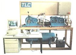
| printable version | Piston compressor | |||||||||||||||||||||||||
| Piston compressor double stage HG002 | Piston compressor double stage HG004 | ||||||||||||||||||||||||||
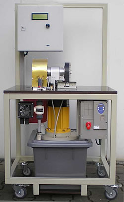
| The stages of compression are distributed on two separate machines. By variation of their speed it is possible to change the stage pressure relations within wide limits. Controlled inter- and after-water-cooling and cylinder air-cooling provides adjustment of all variations of performance. Indicating determines the internal work automatically. | |||||||||||||||||||||||||
Compressors:
The two compressors can be operated in single-, series-
and parallel circuit. | ||||||||||||||||||||||||||
Measuring systems : The measuring devices are digitally connected to the internal controller, sending data to the comprised portable PC. Stand control and data acquisition is performed by Windows-software. Measured quantities are:
| ||||||||||||||||||||||||||
Technical details: Dimensions: 3m x 1.8m x 0.65m | ||||||||||||||||||||||||||
Supplies: 400V 3-phase AC 2.5 kW, cooling water | ||||||||||||||||||||||||||
| ||||||||||||||||||||||||||
| Piston compressor double stage HG004 | ||||||||||||||||||||||||||
| The stages of compression are distributed on two separate machines. By variation of their speed it is possible to change the stage pressure relations within wide limits. Together with the controlled inter- and aftercooling all variations of performance can be adjusted. Indicating determines the internal work automatically. | |||||||||||||||||||||||||
Compressors:
The two compressors can be operated in single-, series-
and parallel circuit. | ||||||||||||||||||||||||||
Measuring systems: The measuring devices are digitally connected to the internal controller, sending serial data to the comprised portable PC. Stand control and data acquisition is performed by Windows-software. Measured quantities are:
| ||||||||||||||||||||||||||
Technical details: Dimensions: 3m x 1.8m x 0.65m |
||||||||||||||||||||||||||
Supplies: 400V 3-phase AC 2.5 kW |
||||||||||||||||||||||||||
| top | ||||||||||||||||||||||||||
Keywords: Air Compressor, Piston
Compressor, Reciprocating Compressor, Double Stage Compressor, Compressorium,
Indicating |
||||||||||||||||||||||||||
| ©TeLC Unna 2004 | ||||||||||||||||||||||||||
| printable version | Fluid mechanics | ||||||
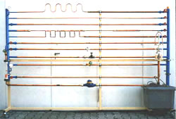
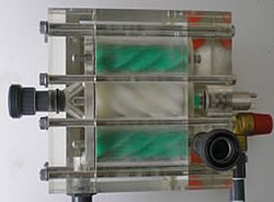
| This new designed test-stand provides a great number of experiments concerning losses caused by friction and restriction in dynamic fluids. Further forces are measured caused by 90° and 180° deflections. Build-up: The unit consists of:
| ||||||
| |||||||
| |||||||
Keywords: Fluid dynamics, losses,
friction, restriction |
|||||||
| ©TeLC Unna 2004 | |||||||
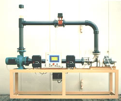
| printable version | Pump test stand | ||||||||
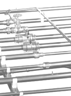
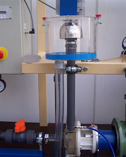
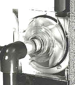
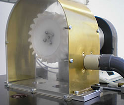
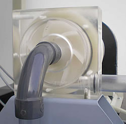
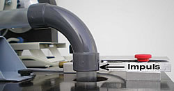
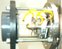
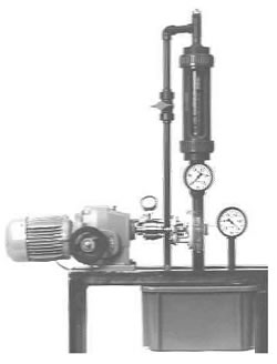
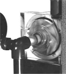
| Test stand bases on a transparent
centrifugal pump with measuring systems to determine its characteristics.
The impeller is visible and can be interchanged quickly with another different
impeller type. Further it is possible to perform fluid dynamical investigations
on elements like pipe bends, elbows, reductions, expansions, valves, nozzles,
ventury tube, pitot-static tube. Measuring systems : The measuring devices are digitally connected to the internal controller, sending serial data to the comprised portable PC. Stand control and data acquisition is performed by Windows-software. Measured quantities are:
| ||||||||
| |||||||||
| |||||||||
Keywords: Centrifugal pump,
Pump characteristics, characteristic values of pump, Fluid circuits, fluids
dynamics, waterflow, Valve characteristics, Characteristics of fluid dynamic
elements |
|||||||||
|
New: |
||||||||
| ©TeLC Unna 2004 | |||||||||
| printable version | Pelton Teststand | ||||||||
| Teststand contains principles of water working- and power machines in singular way. The housings are transparent. Measure and control -technics: Measure data are read on display or on PC screen. Seriall data transfer see Windows-program Water brake is supplied separately for use with other machines. Technical Data of the brake: power 1,5- 25 kW speeds up to 10000 rpm
| ||||||||
|
| ||||||||
|
| ||||||||
| ©TeLC Unna 2004 | |||||||||
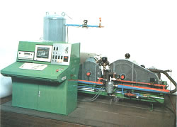
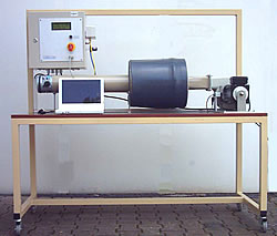
| printable version | Pump-turbine | |||||||
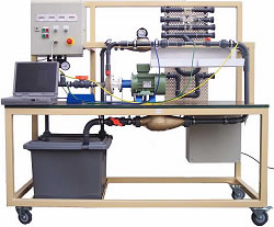
| This moveable test stand bases on a pump-turbine with variable, during run adjustable blades in rotor and stator. The Centrifugal pump in the circle is the feeder-pump. It serves also as restrictor and operates as a (non-perfect) centripetal turbine. Flow (Cavitation)- observations can be made through the perspex pipe section. The 4-quadrants frequency speed control for the axial- and radial-machine makes a restrictor valve dispensable and allows axial pump performance near zero pressure. Pump turbine aggregate: | |||||||
Measuring systems: The measuring devices are digitally connected to the internal controller, sending serial data to the comprised portable PC. Stand control and data acquisition is performed by Windows-software. Measured quantities are:
| ||||||||
| Technical details: | ||||||||
| ||||||||
Keywords: Pump turbine, Turbine
, Water turbine, Reversible Axial Pump Turbine, Axial Pump Turbine |
||||||||
| ©TeLC Unna 2004 | ||||||||
| printable version | Pump-turbine aggregate | |
| The axial type hydraulic machine is the predestined object for studies in mechanical and civil engineering. Incorporated in a pipework, with supply pump or vessel in some height and equipped with flow-meter and pressure transmitter then a test stand is created which is an ideal field for basic experimenting. Technical details:
| |
| ||
Supply: 3~ 400V , 4 kW | ||
Please have a look at our complete "Pump-turbine test stand". | ||
Keywords: Pump turbine, Turbine
, Water turbine, Reversible Axial Pump Turbine, Axial Pump Turbine |
||
| ©TeLC Unna 2004 | ||
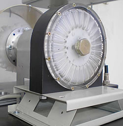
| printable version | Teststand radial fan | |||||||
| Teststand Radial Fan to determine the characteristica icluding efficiency at all speeds | |||||||
| With connection of a PC through serial terminal all the functions of the TLC software can be used. See following page and Windows-software | ||||||||
|
||||||||
|
||||||||
Stichworte: Wärmeverlust, Isolierstoffe, Isolierung, Wärmedurchgang, Versorgungstechnik, Gasgebläsebrenner Simulator, Gasgebläsebrenner Testanlage, Gasgebläsebrenner Übungsstand, Gasgebläsebrenner Ausbildung, Heizungstechnik, Heizung, Fußbodenheizung, Radiatorheizung, Luftbefeuchter, Testanlage, Übungsstand, Ausbildung, lehrmittel, technische, Schulen, Berufsschulen, Universitäten, Fachhochschulen, Weiterbildung, Qualifizierung, Laborgerät, Prüfstand, Versuchsstand, Übungsgerät, Lehrgerät, Demonstration, Modell, Lehre, Bildung, Ausbildung, Schulung, Weiterbildung, Training, Lüftungsbauer, Zentralheizungs- u. Lüftungsbauer, Rohrleitungsmonteur, Klimatechniker, Gas- und Wasserinstallateur, Kältenanlagentechniker, Gasinstallateur, Sanitärtechniker, Heizungsinstallation, Wärmeverlust, Isolierstoffe, Isolierung, Wärmedurchgang, Wärmetauscher, Kreuzstrom, Gegenstrom, Gleichstrom, Platten, Röhren, Rohrbündel, Testanlage, Übungsstand, Ausbildung, lehrmittel, technische, Schulen, Berufsschulen, Universitäten, Fachhochschulen, Weiterbildung, Qualifizierung, Laborgerät, Prüfstand, Versuchsstand, Übungsgerät, Lehrgerät, Demonstration, Modell, Lehre, Bildung, Ausbildung, Schulung, Weiterbildung, Training, Lüftungsbauer, Zentralheizungs- u. Lüftungsbauer, Rohrleitungsmonteur, Klimatechniker, Gas- und Wasserinstallateur, Kältenanlagentechniker, Gasinstallateur, Sanitärtechniker, Heizungsinstallation |
||||||||
| ©TeLC Unna 2004 | ||||||||
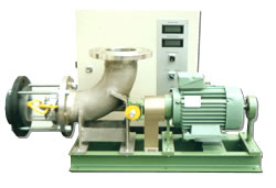
| printable version | Centrifugal pump | ||||||||||||||||||||
| Test stand bases on a transparent centrifugal pump with measuring systems to determine its characteristics. Technical details of pump:
Further properties :
| ||||||||||||||||||||
| |||||||||||||||||||||
Keywords: Centrifugal pump,
Pump characteristics, characteristic values of pump, Pump test cell, Pump
test stand |
|||||||||||||||||||||
| ©TeLC Unna 2004 | |||||||||||||||||||||
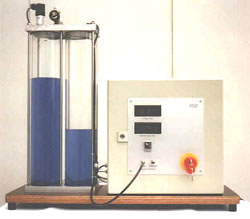
| printable version | Boil-Mariotte-device | |
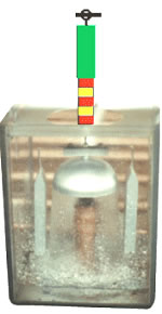
| Device for Verification of Boil Mariotte´s law: p x V =constant Description: | |
| Measure system: pressure: piezoresistive absolut Volume: sonical through bottom and water column Indication on LCDs Serial data terminal for acquisition with adapted Windows-Programm. |
||
| Dimensions: Column dia 100 mm length 500 mm |
||
Stichworte: Boil, Mariotte,
Boil-Mariotte |
||
| ©TeLC Unna 2004 | ||